 So you bought a new pedal, played around with it and a few days later you take a look at the manual. On the last page, you spot some cryptic symbols and lines. A schematic of your pedal showing the internal signal flow. If this is as clear as mud to you, let me help you.
Reading a schematic circuit is probably easier than understanding the London underground map.
Since schematics differ in their details, I refer to the symbols we use in our signal flow diagrams.
Let’s start!
1. Simple connection
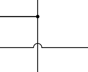
This is a typical connection between 2 components. If you spot a dot, it means it’s connected. If the line is bent over the other one, it means there’s no connection. Sometimes it’s not even bent, but when there’s no dot it has no connection.
2. TS jack socket
It’s a socket where you connect your instrument, the amplifier or pedals – depending on the label. This here is a TS version, meaning Tip and Sleeve. Usually, we call it a ”mono“ jack. There are TRS (Tip Ring Sleeve) versions as well and although in all of our pedals we use TRS jacks (because they are super reliable as they have more pins soldered to the pcb), it’s possible that in the schematic a TS connection is shown.
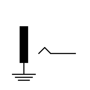
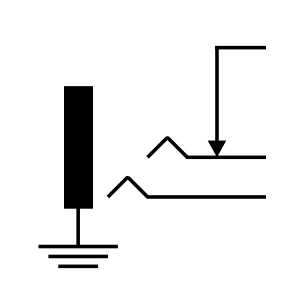
3. TS jack socket with switching
This is the same as the one above, but it offers a switching function. So what does it do? If the jack is occupied, meaning there’s a connector in it, it takes the signal coming from the connector. If it’s not occupied it’s connected to the signal coming from the line with the arrow. So your plug is actually a switch. This has a lot of applications, e.g. the moment you plug in the connector you don’t have to turn a switch manually, but it activates its switch function automatically. In the LITTLE DUAL and DUAL SGoS we take advantage of the switching function: the moment you connect a plug to the A socket, the main signal connected to A/B, (DUAL SGoS: A/B/T) isn’t sent to output A anymore. but to B (DUAL SGoS: and T) only.
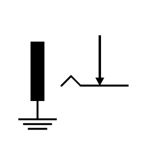
4. TRS jack socket with switching
Again here’s a socket with switching function, but it has one more pin: the ring. Usually, TRS sockets are used for stereo signals (Tip: left; Ring: right; Sleeve: ground) or balanced signals (Tip: positive; Ring: negative; Sleeve: ground). So depending on the pedal, it carries a stereo or balanced signal. At LEHLE we are using the TRS sockets for midi as well. Confused? Read everything about ”TRS: Balanced or Stereo or what“ here.
5. Potentiometer
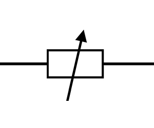
This symbol shows a potentiometer. Depending on how it’s labelled it controls volume, mixes or is part of an EQ etc.
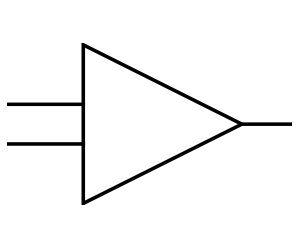
6. Amplifier
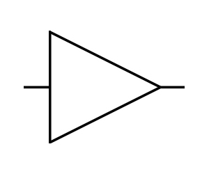
Since all the components above are passive ones, this is the first active device. It is mostly used to change the impedance, so it’s a buffer. Yes, you read correctly. The magic word ”buffer“. What’s a buffer and do you need one? Check this post.
7. Amplifier with balancing/unbalancing
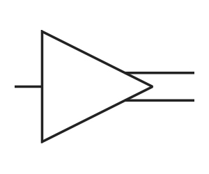
There are a lot of applications for an active circuit. Here you can see a) balancing a signal and b) unbalancing a signal. We use this in the PARALLEL L for example.
8. Amplifier with control
Of course, it’s important to be the loudest in the band, but sometimes it’s necessary to adjust the volume. Here you see an amplifier with control. Usually, it’s a simple potentiometer in combination with the active circuit, but to keep schematics clear they are shown as one component.
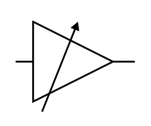
9. Voltage Controlled Amplifier

Now it gets interesting: a VCA (voltage controlled amplifier) doesn’t need a potentiometer; it needs voltage to change the volume! Those ”control voltages“ are common in compressors or synthesizers and control the VCA. We use them in our VOLUME PEDALS to change the volume, allowing them to operate wear-free.
10. Programmable Hall Sensor
You are probably asking yourself where does a control voltage come from? The Hall sensor is a good example. It doesn’t supply a ”hall“ reverb, but it’s named after his inventor, Edwin Hall. A Hall-sensor measures its distance from a magnet and changes the voltage flow. Here you have the control voltage for your VCA.
11. Switch
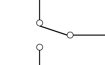
Here you can see a simple switch. There are a lot of different switching symbols, but this one is probably the most common. It’s easy: A or B. Either black or white. If there are more switches shown, it can still be one component, even when different functions are assigned to it (2pdt, 3pdt, 4pdt, etc). E.g. a switch can toggle one or more signals and at the same time switch an LED or an output.
12. Ground Lift
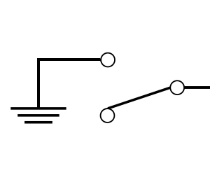
If you see this symbol, it’s the ground switch. If there’s hum or an annoying buzz you can lift the ground connection from (usually) the output. Don’t worry: it’s not dangerous as long as your amplifier has a proper earth connection (which it should always have!).
13. Transformer
![]()
If you don’t have a ground lift, then you might need a transformer, the ultimate weapon for eliminating hum. There are a lot of different transformers with different applications out there, but at LEHLE we use them to transfer a signal without a galvanic connection, so you can use your multiple amps at once. How? Check the post Dual Amping, Stereo, Phasing and its challenges. Transformers can be used for balancing a signal and they also protect you and your gear from unwanted voltages like phantom power or lightning strikes. I’m not joking. The P-SPLIT II is a handy tool to always carry in your gig-bag.
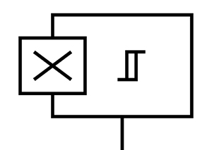
14. ?
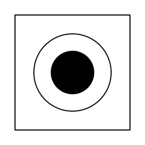
If you spot this symbol somewhere in a schematic, you have a washing machine on board. Congratulations.
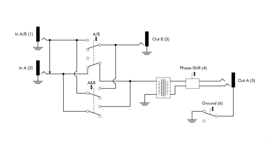
Now that you’re an expert in schematic reading, below are a few examples out of our schematic in the manuals. Have fun and always follow the white rabbit signal.
If you need help: write to support@lehle.com